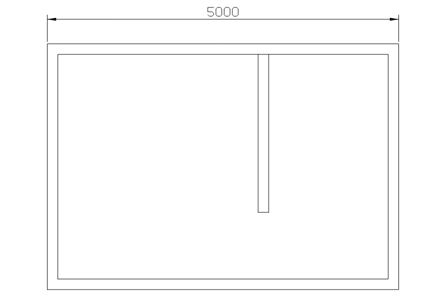
Draw the room outline and walls
Open the editor on a computer with a keyboard and choose New drawing. Work in model space and use one drawing unit per millimeter. Click the command line, enter each command or coordinate below, and press Enter after each line. Skip the blank lines that separate commands.
The first rectangle sets the outside corners. The second sits 150 mm inside all four edges. If the room extends beyond the visible area, type ZOOM, press Enter, then type E and press Enter to fit the drawing.
RECTANG
0,0
5000,3500

RECTANG
150,150
4850,3350Add an internal partition and leave a passage
Draw the partition as two vertical edges with a 150 mm gap between them. Both edges meet the inner wall at y = 3350 and stop at y = 1100, leaving a 950 mm passage to the inner bottom wall at y = 150. A short line caps the open end of the partition.
Where you see ↵ on its own line, press Enter once at the empty command prompt to finish the current LINE command.
LINE
3000,1100
3000,3350
↵

LINE
3150,1100
3150,3350
↵

LINE
3000,1100
3150,1100
↵
Place and verify a width dimension
Set DIMSCALE to 50 so the labels and arrows are readable at this drawing size. Use DIMLINEAR with the upper outside corners and place the dimension above the room. The result should read 5000 mm. If it differs, recheck the two corner coordinates.
If you develop the plan further, separate walls, fixtures and annotation onto different layers so you can review them individually.
DIMSCALE
50

DIMLINEAR
0,3500
5000,3500
2500,3850
Save the plan as DXF and share a preview
Select Download DXF and reopen the saved file in the viewer to verify the two rectangles, the partition and the dimension. Compare the geometry with the downloadable practice file below. The separate studio example adds furniture, doors and room labels to show how a fuller plan can be organized.
Send the DXF for further editing. For a presentation or feedback, export SVG for a scalable image or PNG for a fixed view.